Thursday 28 March 2019

Stereo Photography

At the end of the last century (!) I bought a power winder for what was then my main camera, an Olympus OM-2 SP.  Next to the trigger button on this winder was a small jack socket which connected in parallel with the buttton switch, so that you could plug in a cable with another switch at the far end and use that as a remote release, a simple  method that worked well.  It occurred to me that by connecting two winders together using this socket, you could get two cameras to take a photo simultaneously by pressing just one of the winder buttons.  This turned out to be the case.  Why would I want to take two photos simultaneously?  Stereo Photography :  Take two photos with cameras separated by a short distance and, when you have the developed & printed (or scanned) images, show the one from the left-hand camera to the viewer's left eye and the one from the right-hand camera to the viewer's right eye.  They will see an image in 3-D, i.e. with depth perception.  As it is difficult to get two cameras as close together as anyone's eyes are, it is usually an enhanced depth perception.

It could get expensive, needing two cameras with the same lenses, but by using obsolete 2nd hand gear, I was able to keep it affordable.

Using a pair of OM-2SPs plus winders on a simple horizontal bar worked well, and still would if I were to source some film and resurrect that rig, which I could do since I still have all the parts.

In the digital age, I replaced the film cameras with a pair of Minolta A-1s (when they were several years old and therefore inexpensive).  Once again, it was possible to use a simple lead which connected the pins on one socket on the back of one camera to the same pins on the corresponding socket of the second, allowing the shutter release button of one camera to control both cameras.  Sadly, one of the A1s succumbed to the infamous sensor defect, and, even more sadly, did so after Sony had stopped replacing the defective sensors FOC.

So I gave up stereo photography until earlier this year (2019), when I noticed that very affordable Olympus E-600s had started appearing on eBay.  It looked like the same method of linking them would work, they're very compact for digital SLRs and I had an idea about 3-D printing a bracket that would allow me to switch from landscape to portrait orientation at will.  A working prototype of the rig is shown below in portrait orientation.  I'm calling it a working prototype because it does work, although a few things could be improved for the next attempt. It hinges around the bolt at the top with the wing nut.  The two small screws to the right of the wing nut allow a bit of adjustment of the alignment when they are horizonal.


The coiled cables are adapters for a multi-function cable release & timer, which can be bought separately from the device itself.  It was either that or buy a couple of cheap cable releases and cut off the cables.


Here's the view from the back, showing the cables plugged into the cameras' multi-function ports.  The cables came with 3-way 3.5mm jack plugs on their other ends, which I plugged into a pair of sockets that you can see in the top-right corner of the camera bracket.  I was hoping to be able simply to connect these together and use either of the cameras' release buttons to trigger both cameras, as with the previous arrangements, but this turned out not to be possible for reasons I've not been able to fathom.  A bit of poking around with a test meter revealed that two of the jack terminals have small positive voltages relative to the third, and connecting one of those to the 3rd terminal activates the autofocus & metering system (i.e, that's equivalent to a half-press of the shutter release) and connecting both to the 3rd terminal releases the shutter (i.e. a full press of the shutter release).  using a couple of diodes to isolate the cameras from each other and using a pair of momentary action push buttons (bottom-left corner of the camera bracket)  allowed for triggering both cameras at once.  It's not the most ergonomic solution possible, but it works.


Above are shown the buttons & jack sockets on the underside of the rig in landscape orientation.


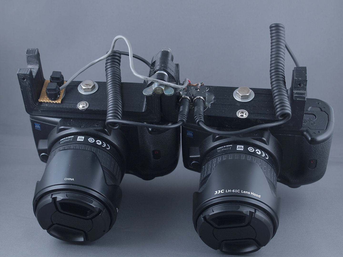
Above is the whole thing in landscape orientation.  You can probably tell from this that the 3-D printing had some bed adhesion issues, but it didn't detach completely and has turned out to be useable as it is.  That's the other main area of improvement for the next version, along with devising some way of adjusting the cameras' alignment.

Finally for now, some stereograms.  These are all red/cyan anaglyphs (i.e. you need glasses with a red filter over the left eye and a cyan filter over the right eye) and mostly monochrome. Firstly, we have here a picture of my old OM-1


I'm rather pleased with this, despite the front of the lens not looking quite right, since it was taken with flash lighting at 1/100 s, triggered from the right-hand camera.  I find that pleasing because the cameras need to be synchronised to within about 1/250s for that to work properly - otherwise the left-hand camera would have a dark band at the top or bottom of the image where the shutter either hasn't finished opening yet or has started closing already.

Secondly, here are some pictures around my place of work:

https://photos.app.goo.gl/4YNHieqRQwKkpzF48

And here are some taken at a gig:

https://photos.app.goo.gl/nfXSwmFnyUm8N9Rq9


Friday 8 March 2019

Old School Light Chaser part 2

As promised, some more details of the construction.  Above is the circuit diagram, repeated from the last post.  The area highlighted in grey is one LED segment, construction of which is detailed below.


First, the base-emitter resistor and diode are wrapped together like this.


Then they're soldered together and the resistor leads bent into loops like this.
Then the pair of them are soldered to the base & emitter of the transistor.


 A second sub-assembly comprising the capacitor and LED is assembled like this
 Then the two sub-assemblies are combined like this.  Note that the capacitor & LED have been turned over since the previous photo.

Then the LED resistor and capacitor resistor are added like this.


Then exposed parts are covered in heat-shrink sleeving to prevent accidental short circuits, leaving only the ends of the leads exposed.


When enough of these have been made, they can be connected together and covered with more heat-shrink sleeving.  The first one in the string has a push-to-make button switch connected across the transistor's collector and emitter, and the output of the last LED segment is looped back to the input of the first.  The finished segments are about the same size as traditional Christmas tree lights, which is what I've been using them for.

Wednesday 6 March 2019

Old-School Light Chaser

This is based on a very old circuit, first published in the 1960s with germanium transistors and using small incandescent light bulbs.  At the time it was published, the only LEDs available were large red things (think HAL9000 from 2001, a Space Odyssey) that cost about £50 each.  A string of 48 of those would have cost you the price of a nice car.  A new one.  I rediscovered this in a document I found on the internet one day, which you can see here - it's the second circuit in the list.  Below is the schematic.

There's a good description of how it works in the link.  It's based on a circuit called an 'astable multivibrator', which is basically a 2-stage common emitter amplifier, capacitor coupled between the stages and with the output of the second stage fed back (also through a capacitor) to the input of the first stage.  The circuit here simply adds extra stages and some emitter to base diodes which prevent the transistors' base-emitter junctions from going into reverse breakdown.

I thought it would be neat to adapt this to use LEDs and build a long string of them, running on, say, 12V because I had several 12V wall-wart type power supplies doing nothing at the time.  I opted to use red, green & blue LEDs, 16 of each making a total of 48.  Using BC337s for the transistors (they were the cheapest I could get hold of, at about 2p each from CPC if you bought a bag of 100) and running on 12V, I found that there was enough leakage through the capacitors to keep the transistors slightly conducting, so added a bleed-off resistor in parallel with the diodes to fix that.

I've also added a switch to control the sequence - bypassing the transistor of the first stage will switch that light on and prevent the second stage (and therefore subsequent stages) from triggering.  By closing and re-opening the switch you can send extra 'pulses' down the line.

Here's a video of the light chaser just before the final assembly & covering with heat-shrink.

Since making the first one, I've tweaked the circuit a little, so now it's as shown below.  Capacitors are 10 microfarad electrolytics.  More construction details to follow in the next post.