New Z-axis Lead Screws
Another thing I was never happy about with the Copymaster 300 was the z-axis lead screws. As supplied, these were 4-start 2mm pitch screws, giving a lead (i.e. length of travel per revolution) of 8mm. This is far too coarse for a z-axis in my view. The z-axis does not need to move quickly, a few mm per second (i.e. <=10) is more than enough. What it does need to do is move precisely and repeatably, ideally with a resolution of 10 microns or better. It also needs to stay where it is when the motors are not energised, and that was the big problem I experienced: with the x-carriage at or near the home position, the weight of the two stepper motors (x-axis & extruder), plus hot end plus the carriage itself plus the gantry was enough to rotate the z-axis and allow that end of the gantry to fall by a significant fraction of a millimetre when the motor current was turned off. Usually. This meant levelling the gantry again every time the printer was used, which was a tedious chore. I decided to change the lead screws to something with a finer pitch.
First, I ordered some single start 1mm pitch lead screws and nuts from China. They managed to send me the right nuts, but the wrong lead screws. The screws turned out to be a 2-start 2mm pitch thread (i.e. 4mm lead per revolution). That would probably have worked, but, not having any nuts to go with them, I decided to hedge my bets and order another pair of 1mm lead screws from another supplier, and some 2mm, 2-start nuts to go with the wrong lead screws. I was bound to get something that would work, I hoped. I can always use the leftovers for something else. Don't yet know what, stay tuned.
In the meantime, I went to my local screwfix and bought a couple of lengths of M8 threaded rod, which has a pitch of 1.25mm, and made some anti-backlash nuts using standard M8 nuts, springs and some printed parts. That actually worked really well, and I should probably have done it that way in the first place. I've now got the 1mm lead screws I intended to use, and made another pair of anti-backlash nuts to go with them.
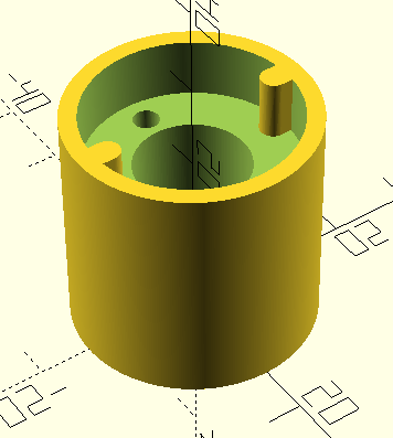
Here's the OpenSCAD design for the anti-backlash system. two of the lead screw nuts were modified slightly to make this work: two of their fixing holes were cut into slots so that they would engage the two lugs visible at the top of this part, preventing them from rotating with the lead screw whilst allowing the small vertical movement needed to allow the spring to push them against the thread.
Here's the finished item in-situ. Next time I might make it so you can see the spring inside.


No comments:
Post a Comment