Thursday, 28 March 2019

Stereo Photography

At the end of the last century (!) I bought a power winder for what was then my main camera, an Olympus OM-2 SP.  Next to the trigger button on this winder was a small jack socket which connected in parallel with the buttton switch, so that you could plug in a cable with another switch at the far end and use that as a remote release, a simple  method that worked well.  It occurred to me that by connecting two winders together using this socket, you could get two cameras to take a photo simultaneously by pressing just one of the winder buttons.  This turned out to be the case.  Why would I want to take two photos simultaneously?  Stereo Photography :  Take two photos with cameras separated by a short distance and, when you have the developed & printed (or scanned) images, show the one from the left-hand camera to the viewer's left eye and the one from the right-hand camera to the viewer's right eye.  They will see an image in 3-D, i.e. with depth perception.  As it is difficult to get two cameras as close together as anyone's eyes are, it is usually an enhanced depth perception.

It could get expensive, needing two cameras with the same lenses, but by using obsolete 2nd hand gear, I was able to keep it affordable.

Using a pair of OM-2SPs plus winders on a simple horizontal bar worked well, and still would if I were to source some film and resurrect that rig, which I could do since I still have all the parts.

In the digital age, I replaced the film cameras with a pair of Minolta A-1s (when they were several years old and therefore inexpensive).  Once again, it was possible to use a simple lead which connected the pins on one socket on the back of one camera to the same pins on the corresponding socket of the second, allowing the shutter release button of one camera to control both cameras.  Sadly, one of the A1s succumbed to the infamous sensor defect, and, even more sadly, did so after Sony had stopped replacing the defective sensors FOC.

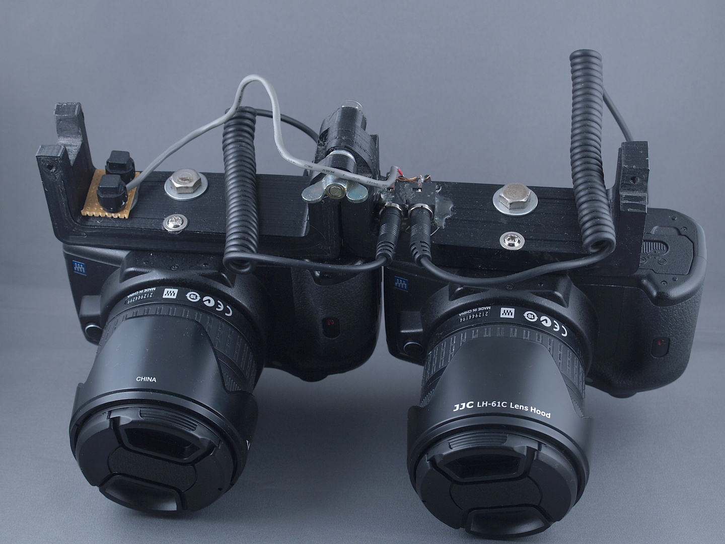
So I gave up stereo photography until earlier this year (2019), when I noticed that very affordable Olympus E-600s had started appearing on eBay.  It looked like the same method of linking them would work, they're very compact for digital SLRs and I had an idea about 3-D printing a bracket that would allow me to switch from landscape to portrait orientation at will.  A working prototype of the rig is shown below in portrait orientation.  I'm calling it a working prototype because it does work, although a few things could be improved for the next attempt. It hinges around the bolt at the top with the wing nut.  The two small screws to the right of the wing nut allow a bit of adjustment of the alignment when they are horizonal.


The coiled cables are adapters for a multi-function cable release & timer, which can be bought separately from the device itself.  It was either that or buy a couple of cheap cable releases and cut off the cables.


Here's the view from the back, showing the cables plugged into the cameras' multi-function ports.  The cables came with 3-way 3.5mm jack plugs on their other ends, which I plugged into a pair of sockets that you can see in the top-right corner of the camera bracket.  I was hoping to be able simply to connect these together and use either of the cameras' release buttons to trigger both cameras, as with the previous arrangements, but this turned out not to be possible for reasons I've not been able to fathom.  A bit of poking around with a test meter revealed that two of the jack terminals have small positive voltages relative to the third, and connecting one of those to the 3rd terminal activates the autofocus & metering system (i.e, that's equivalent to a half-press of the shutter release) and connecting both to the 3rd terminal releases the shutter (i.e. a full press of the shutter release).  using a couple of diodes to isolate the cameras from each other and using a pair of momentary action push buttons (bottom-left corner of the camera bracket)  allowed for triggering both cameras at once.  It's not the most ergonomic solution possible, but it works.


Above are shown the buttons & jack sockets on the underside of the rig in landscape orientation.


Above is the whole thing in landscape orientation.  You can probably tell from this that the 3-D printing had some bed adhesion issues, but it didn't detach completely and has turned out to be useable as it is.  That's the other main area of improvement for the next version, along with devising some way of adjusting the cameras' alignment.

Finally for now, some stereograms.  These are all red/cyan anaglyphs (i.e. you need glasses with a red filter over the left eye and a cyan filter over the right eye) and mostly monochrome. Firstly, we have here a picture of my old OM-1


I'm rather pleased with this, despite the front of the lens not looking quite right, since it was taken with flash lighting at 1/100 s, triggered from the right-hand camera.  I find that pleasing because the cameras need to be synchronised to within about 1/250s for that to work properly - otherwise the left-hand camera would have a dark band at the top or bottom of the image where the shutter either hasn't finished opening yet or has started closing already.

Secondly, here are some pictures around my place of work:

https://photos.app.goo.gl/4YNHieqRQwKkpzF48

And here are some taken at a gig:

https://photos.app.goo.gl/nfXSwmFnyUm8N9Rq9


Friday, 8 March 2019

Old School Light Chaser part 2

As promised, some more details of the construction.  Above is the circuit diagram, repeated from the last post.  The area highlighted in grey is one LED segment, construction of which is detailed below.


First, the base-emitter resistor and diode are wrapped together like this.


Then they're soldered together and the resistor leads bent into loops like this.
Then the pair of them are soldered to the base & emitter of the transistor.


 A second sub-assembly comprising the capacitor and LED is assembled like this
 Then the two sub-assemblies are combined like this.  Note that the capacitor & LED have been turned over since the previous photo.

Then the LED resistor and capacitor resistor are added like this.


Then exposed parts are covered in heat-shrink sleeving to prevent accidental short circuits, leaving only the ends of the leads exposed.


When enough of these have been made, they can be connected together and covered with more heat-shrink sleeving.  The first one in the string has a push-to-make button switch connected across the transistor's collector and emitter, and the output of the last LED segment is looped back to the input of the first.  The finished segments are about the same size as traditional Christmas tree lights, which is what I've been using them for.

Wednesday, 6 March 2019

Old-School Light Chaser

This is based on a very old circuit, first published in the 1960s with germanium transistors and using small incandescent light bulbs.  At the time it was published, the only LEDs available were large red things (think HAL9000 from 2001, a Space Odyssey) that cost about £50 each.  A string of 48 of those would have cost you the price of a nice car.  A new one.  I rediscovered this in a document I found on the internet one day, which you can see here - it's the second circuit in the list.  Below is the schematic.

There's a good description of how it works in the link.  It's based on a circuit called an 'astable multivibrator', which is basically a 2-stage common emitter amplifier, capacitor coupled between the stages and with the output of the second stage fed back (also through a capacitor) to the input of the first stage.  The circuit here simply adds extra stages and some emitter to base diodes which prevent the transistors' base-emitter junctions from going into reverse breakdown.

I thought it would be neat to adapt this to use LEDs and build a long string of them, running on, say, 12V because I had several 12V wall-wart type power supplies doing nothing at the time.  I opted to use red, green & blue LEDs, 16 of each making a total of 48.  Using BC337s for the transistors (they were the cheapest I could get hold of, at about 2p each from CPC if you bought a bag of 100) and running on 12V, I found that there was enough leakage through the capacitors to keep the transistors slightly conducting, so added a bleed-off resistor in parallel with the diodes to fix that.

I've also added a switch to control the sequence - bypassing the transistor of the first stage will switch that light on and prevent the second stage (and therefore subsequent stages) from triggering.  By closing and re-opening the switch you can send extra 'pulses' down the line.

Here's a video of the light chaser just before the final assembly & covering with heat-shrink.

Since making the first one, I've tweaked the circuit a little, so now it's as shown below.  Capacitors are 10 microfarad electrolytics.  More construction details to follow in the next post.

Sunday, 24 February 2019

Mustard Tin Music Players


There's a meme in the world of hobbyist electronics about building projects into an Altoids tin.  Someone has even put an electronics lab into one.  I've chosen to do something a bit different - a Colman's mustard tin.  Two different ones, in fact, a 4 Oz one and a 2 Oz version.  Same sort of project though:  a slimmed-down version of the PiFi network music player which you can read about the evolution of in earlier posts here.


The 4 Oz version

Having upgraded my PiFi to use a Raspberry Pi 3 and a different DAC, I was left with a seemingly redundant HiFi Berry DAC that would only work with an original Pi model B (because of the GPIO pin layout, which changed with the B+).  I noticed that the combination of Pi model B and DAC would just fit into a 4 Oz mustard tin, and so a scheme was born to make a more portable version of the PiFi which could be used, say, at a barbecue, powered by a car battery or other 12V source.  It would use a USB flash drive to store the music files as mp3 rather than FLAC and be controllable only via WiFi through a USB adapter (so that's both USB ports used).  Software setup is essentially the same as for the original PiFi, i.e. it boots from the SD card which contains the root file system and mounts the USB flash drive at start-up.   USB flash drive is formatted as NTFS to make it easier to load music onto it.  There's still a samba server running so you can do file management over WiFi, but plugging the USB drive into a PC is much easier & quicker.  Logitech Media Server handles the user interface and Squeezelite handles the playing of music. To make it fit into the tin, I did have to cheat a bit with the SD card.  Pi 1 uses a full-size card which sticks out too far at the bottom, so I've used a micro SD card and a small format adapter, which doesn't stick out at all. You can see it in the photo above.  Also visible above is the DC-DC  converter to drop the 12V input down to 5V - it's inside the black heat-shrink just inside the open end of the tin.

I happened to have some yellow PLA, so I printed a new lid for the mustard tin to accommodate the USB ports, a shutdown button and a 3-colour LED.  The LED flashes green once the player is booted up and running and turns red  whilst it is shutting down.  There's another printed part in the bottom of the tin to steady the bottom end of the Pi, so it won't accidentally come into contact with the metal walls of the tin.  There's a power socket on one side and a 3.5mm jack on the other.

It's worked well so far, the only glitch is that you can't run it and an amplifier from the same battery, at least not the battery powered amplifier I built to play music in my garage.


The 2 Oz tin

You can't get 4Oz tins of Colman's mustard powder in any of the shops around here anymore, but you can get 2Oz tins, so I also happened to have an empty one of those.  I also happened to notice that Pimoroni were selling a little DAC board using the same chip as the old HiFi Berry, which was exactly the same size as a Raspberry Pi Zero.... and they'd both fit together inside the smaller tin with space to spare for another board with the circuit I used in the PiFi to switch power on & off plus a DC-DC converter.  Pimoroni call their little DAC board a PHAT DAC, PHAT being an acronym for Pi Hardware Attached (on) Top, because it's meant to plug straight onto the GPIO header pins on top of a Pi.  They supply it with a header block, but it's not soldered to the board.  I like this, because a Pi zero also comes without header pins attached, so I was able to save a bit more space by putting the header block on top of the DAC board and putting some right-angled pins on the Pi Zero so they stick out beneath far enough to still make contact with the header block and still allow connection to the top of the Pi.  I suppose this makes it Pi Hardware Attached Beneath - a PHAB DAC.  I also like that.


If I were to do this again, though, I'd modify a set of header pins so that only those I need to connect to for LEDs & shutdown signals would have the right-angled pins, the others would just be straight through to the DAC beneath, and longer.

When I did this, the Pi Zero W was not yet available, plus I'm not sure how well it would work inside a steel tin, so I have a very small WiFi adapter in the lid, connected via a very short USB lead with a type A socket at the adapter end.  At the Pi end, the wires are soldered directly to a micro USB 'shim' like this one.

Here are the reassembled parts ready to go back in the tin.  You may have noticed in the picture above that the inside of the tin is lined with transparent plastic to insulate it from contact with header pins, circuit boards etc.  In fact it's double-insulated by the bit of old milk carton that you can see here.

Like the PiFi, this one has two buttons, a white one to start up and a red one to shut down.  There are also separate red & green LEDs which work the same way as the red & green in the 4 Oz version.

Tuesday, 19 February 2019

GPS Controlled Clock

The Global Positioning System (GPS) relies on a series of very accurate clocks aboard a constellation of satellites whose orbits are well known.  Differences in arrival time of signals from those satellites are used to calculate distance from them and hence geographical position.  This means that, in addition to being a navigation aid, the GPS system is also a very accurate time standard.   Methods of using this to turn a computer into a very accurate  time server are well known - just search the web for "GPS time server" and you should get plenty of examples.  I've done that myself by connecting a GPS receiver to the Raspberry Pi 2 which acts as a DHCP server, DNS, ad-blocker and file server on my home network, but for this project I wanted to make a stand-alone clock.  I have a longer term ambition to use the GPS location to identify the time zone and summer time rules for the clock's location and show the correct time for that location.  For now, it assumes it's in the UK and only corrects for UTC (GMT) / BST.  Note for any would-be burglars or stalkers:  The location displayed in the photo above has been fudged.  I don't live there.

GPS modules such as the one I used here will send UTC time along with the position fix and other data at regular intervals.  Since the serial data link is rather slow, it is uncertain exactly how old the reported time is by the time it has been received.  Typically, a GPS module will transmit data once per second, starting soon after a UTC second boundary, so the the data is unlikely to be more than a second behind the actual time.  We can do better than that, though, if we use a GPS module that also transmits a PPS signal.  PPS stands for "Pulse Per Second" and, as the name suggests it is a pulse which occurs every second, but more than that, it has a very short rise-time (about 10ns) and starts on every UTC second boundary.  By co-ordinating the time data received with this signal, we can get a very accurate time.

The strategy I've used here goes something like this:  receive and interpret the serial data stream from the GPS module (that takes about 0.15s), add 1s to that (takes <1ms) then wait for the next PPS signal before updating the clock display.  It takes about 0.05 seconds for the program to completely redraw the clock display, which is far less than the time taken for a human brain to read & interpret it.

The program is a bit more sophisticated even than that - once a GPS signal has been received, the time data is used to set the computer's clock, thereafter, the display is updated using the computer's internal clock, but that is compared to the GPS time signal and re-synchronised only if it drifts by more than 0.02s.  That way, the clock will continue to work if the GPS signal is lost.  If the signal is lost, the position data is shown in red rather than the usual green.

Inside the Box

The computer used for this project is, once again, a Raspberry Pi Zero.  I love those things - less than a fiver each and more than enough computing power for something like this with a choice of OSes and programming languages.  The screen used is a 5 inch display with, as it says on the back there, 800x480 pixels which gives a nice crisp display and cost about £16 from Amazon.  This one was intended to be used with a model B, the first one, with the 26 pin GPIO headers.  If you plug that into the socket there, the HDMI output will line up nicely with the adapter that sits in the bulge at the top of the case, and that is how the display is, er, displayed.  There is also a touch-screen which uses some of the GPIO pins, but that's not used in this project.   the header pins are also connected to a series of pads on top of the board, and I've soldered some header pins onto some of those to plug in a connector to the socket on the back panel where the GPS module plugs in.  That uses the UART pins plus one other GPIO pin to monitor the PPS signal.  I used a short mini HDMI-HDMI adapter cable to make the HDMI connection to the screen.
Here it is with everything plugged in again. The device plugged into the micro USB port is the receiver for a wireless keyboard & trackpad.  


Here it is back together again, and with the GPS module.  The box for the GPS module was made before I added the socket for high-gain antenna to the module and so it doesn't fit properly and you certainly can't get the lid on.  I've since re-designed that to suit and it looks much neater.

For the OS and programming language I made what might seem an unusual choice.  RISC OS and BBC BASIC.  Make of that what you will.  I've been a RISCOS user since it was called ARTHUR and I've always liked BBC BASIC.  I'm sure I could have written it in Python, but that would be slower and doesn't really offer any advantage that I can see.  BBC BASIC gives me easy access to those nice anti-aliased outline fonts which look pretty good on this display, plus all the OS calls to mess around with time & date strings etc.  One minor glitch was that taking over the whole system to run the program, rather than letting the OS decide how big a time slice to allocate to the clock program) meant that the CPU ran a bit hot and crashed a few times.  Downclocking to 500MHz solved that, and it has been running almost continuously since last summer without crashing at all.

A little aside about BBC BASIC running under RISCOS on just about any ARM-based SoC you can get now:  The instruction cache will hold quite a lot of the BBC BASIC interpreter and the data cache will hold all of this program.  This means that a program like this one, with a fairly small inner loop that just keeps cycling around will give a cache hit rate of close to 100%, so it is not slowed down by the need to read/write to the relatively slow RAM and is therefore astonishingly fast.  Nearly as fast as a compiled language.

Tuesday, 12 February 2019

Painting with Light

You can see the basic idea on the right there - you have a string of individually addressable LED pixels and you use them to display a bitmap image, one column at a time whilst you take a long-exposure photograph.  The result is an image that seems to hang in the air.  You can just see the white stick in my hand which has a string of 144 APA102 LED pixels..

What's an LED pixel?  it's actually 3 LEDs, a red one, a green one and a blue one plus a clever chip which can control the brightness of each one independently, based on a digital data stream.  This usually works something like this; each LED can have one of 256 brightness levels, i.e. brightness is represented by an 8-bit number, so the controller chip needs 24 bits of information to set the pixel's colour.  The chip has two sets of registers, one to store the colour being displayed and a second to temporarily store incoming data.  Once the chip has received its 24 bits, it simply passes any more data on to the next chip, until data stops being sent.  When data stops being sent, the incoming data is copied to the display registers and the pixel changes colour.  That way, all the pixels in a string can change colour at the same time.

A variety of LED pixels are available on the market, some easier to drive than others.  The very inexpensive ones (e.g. WS2812) need data to be sent at a very precise rate with no interruptions and so are very difficult to drive.  The APA102, which I've used here is much easier to drive - data can be sent at at any speed from a few KHz up to several MHz.  The data stream is deemed to have finished if nothing is sent for about half a millisecond, which is quite a long time for a 32-bit microcomputer clocked at around 1GHz.


The box, and what's inside

So, how are these pixels being controlled?  Over on the right you can see the bottom end of the light-painting stick. The yellow box contains a battery, a Raspberry Pi Zero (would have used a Pi Zero W, but they weren't around yet when I built this), a WiFi adapter and a circuit board that shuts off the power when the Pi has been shutdown.  There are also two LEDs and two small button switches.  The white button switches on the power and the red one shuts down the Pi which then switches off the power.  There's a red LED that lights up when the Pi is shutting down and a green one which flashes when it's booted up and ready to go.  There is a third switch on the handle, which triggers the image display.  Press and release that, and an image is displayed once, keep it pressed and the image will display repeatedly.


In this picture you can see a few of the LED pixels.  APA102 combines the three LEDs and the controller into one 5x5mm chip, so the pixels can be packed quite closely.  There is a version in a 2x2mm package, but they're a bit harder to find, plus, at that density it gets quite expensive producing a decent sized pixel string.  You can also see the battery, comprising three 18650 lithium ion cells connected in series.


Here's a close-up of the circuit board.  Raspberry Pi uses 3.3V logic levels but the APA102 needs 5V logic levels.  The little black chip on the right of this bit of stripboard provides the necessary level shifting.

In the centre of the board are two of the MP1584 DC-DC converters I mentioned in my previous post about the PiFI.  These step down the battery voltage from the 12.6V  of the fully charged lithium cells to 5V. One of them supplies the Pi Zero and the level shifter, the other powers the LED string. I used two of them to spread the load a bit and to isolate the Pi's power supply from voltage fluctuations due to the LED string changing brightness.  144 pixels can cause quite a large current drain at 30mA per pixel.  Fortunately, full white on all the pixels doesn't happen often, or I'd be worried about the survivability of the converter.  


Circuit description

The components on the left of the stripboard control the switching off and on, the schematic is shown  here.  Here's how that works.  S1 is the white button - press that and Q1 will be biased into conduction which will pull the gate of M1, a p-channel MOSFET, down below the supply rail voltage making it conduct. This will supply power to the external circuit (our Pi Zero) and also maintain the base-emitter voltage of Q1 so that the circuit latches on.

Pressing S2 sends a signal to one of the Pi's GPIO pins.  That pin is monitored by a python script running in the background, when it goes high, the script sends another GPIO pin, connected to the "shutdown now" input high then it issues a shutdown command.  When the "shutdown now" input goes high, that momentarily increases the base voltage of Q1, which is already conducting so this doesn't make any difference now.  C3 will now discharge through R4 and the base of Q1, returning the base voltage to normal.  When the Pi has finished shutting down, all its GPIO pins will go low, allowing C3 to pull the base voltage of Q1 low enough to shut it off.  When Q1 shuts off, the voltage at the gate of M1 will rise to the point where M1 will shut off, disconnecting the Pi from the battery and preventing the circuit from latching on again - in other words, the Pi will have switched itself off.

Software

The Pi Zero is running Raspbian Jessie Lite.  It is configured to act as a WiFi access point using hostapd with dnsmasq performing the twin duties of DHCP server and DNS.  There is also a Samba share.  You can't connect to the internet this way, and that was never my intention. This simply provides a way to upload pictures to display and to change which one will be displayed.  The Samba share allows file management from a mobile device, WiFi connection allows a command line via SSH.

Two python scripts are run at startup - one runs in the background and checks for the shutdown button being pressed, the other handles the displaying of images.

Displaying images

The program for displaying images  is a python script which will only ever display one image - an image called "showthis.png".   The program loads this when it starts, then waits for the trigger button to be pressed before displaying it one column at a time  on the pixel string.  Once it has been displayed it will be re-loaded.  This provides a simple way to  change the image to be displayed - rename or copy the one you want to display to "showthis.png" and press the trigger once to 'flush out' the old image, and load the new one.

Generating Images

Not a lot of point having this if you have nothing to display.  I use a vector drawing program such as Inkscape on Windows or Linux machines, Draw+ or Vector on RISCOS systems and then either screen grab the bit I want or export the drawing as a bitmap.  In either case, the result is a bitmap image that can then be resized so that it is 144 pixels high (because that's how many pixels are in the LED string) and uploaded to the Pi Zero via WiFi.


Sunday, 10 February 2019

PiFi gets a Pi-3

Having noted the speed improvement upgrading from a Pi B to a Pi 2, it seemed worthwhile to see what improvement a Pi 3 would make.   The performance of this was quite usable with a Pi model B and much quicker with a Pi 2. Now, with a Pi3, the response is very slick indeed.  I can't tell if the slight delay in updating the server's web page is down to the server or the browser. 

At the same time, I thought I'd see how another DAC board behaved, since they're hardly prohibitively expensive.  This time, I've gone back to HiFiBerry, with their DAC+ PRO.  Sounds excellent to my ears, and a bargain at £32 or so, but then so did the IQ Audio Pi DAC+ previously used so I can heartily recommend either of those to anyone wanting to build a Raspberry Pi based audio player. 

Final change is the addition of a small DC-DC converter so that it can be run from a 12V supply.  It's the little board you can see nearly edge-on to the right of the green button.  I have lots of 12V supplies, so this is a good way to put one of them to good use.   The converter is a little board based on the MP1584 chip.  It works at 1.5MHz so can be very tiny and still have very little ripple, and claims to be good for 3A, though I wouldn't want to run it at that current for long. I took a gamble of buying a lot of 10 of these, (which worked out at <50p each!) from China.  I've used several of them now, and so far they have all worked. They seem to be a good option for powering a Raspberry Pi Zero from batteries - I'll be posting something about that soon. No, really, I made a new-year resolution to update this blog more often.