 |
| New board adapter shown in place. |
There was just one real concern, and that was the MOSFET controlling current to the bed heater. The SKR mini E3 was designed to work with a Creality Ender 3, which has a smaller build bed and therefore a less powerful heater.
MOSFETs and Power Dissipation
 |
| Board mounted on adapter showing underside |
 |
| Board mounted on adapter showing top side |
I couldn't find any sensible information about the Ender 3's bed resistance, power or current draw, but assuming it's going to be about the same as my Mendel, which has a similar bed size, 100W seems about right, which would give a current draw of about 4A since the Ender 3 also works on 24V. Given that I'm drawing more than twice that, the extra heatsinking is pretty essential. In practice, the heatsinks on the mosfets and also the board around them do get very warm, but not worryingly so.
Installation

This is a smaller board than the SKR v1.3, so not surprisingly it went into the printer more easily. Some of the cables needed a bit of re-routing, but everything reached the part it needed to reach. There was just the one hiccup with the screen connection, which I'll come to next. It was never really a possibility that I would be able to position a replacement controller in such a way that I would be able to use the micro SD card slot and the USB connector, so a short flying lead is left permanently plugged into the USB port to allow connection to an external computer. There is also now a short USB extension cable plugged into the USB port on the screen to allow printing from a flash drive via the screen's touch screen interface.
Display & Interface
The TFT24 display connects to the SKR Mini using a serial port for the touch-screen interface and can also connect using the exp1 & exp2 sockets to use the familiar menu-based user interface which employs a rotary encoder and push-button. I quite like the old-style user interface, but the two connectors it requires are not available on this board, so I initially opted for just the touch-screen interface. That is also the only way I can transfer files to the printer via storage device (a USB flash drive in this case). That's not a big deal really, as I continue to drive the printer from a Raspberry Pi running OctoPrint. Then I discovered that there is a way to connect this to a screen and get the old-style user interface. It involves making up a special connector which splits the single 10-way port on the board into two 10-way connectors at the other end. The signals needed are available on that one connector, they're just not in their usual places. This was designed so that the standard Ender 3 screen (which also just uses a single 10-way connector) can be used. This board is meant to be an upgrade for that printer, after all. This does not allow the use of an SD card on the screen since the necessary signals are not present on the screen connector. The Ender 3 has its SD card slot on the mainboard, not the screen so those signals were not needed.
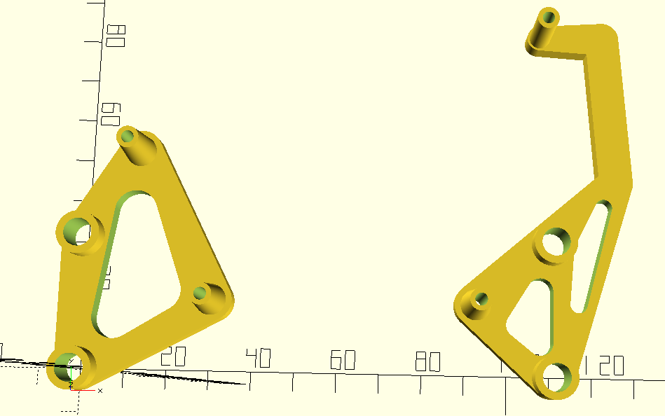 As I like the old style interface, I made up a cable to connect the two boards in that way... which led to the hiccup. Whilst I had left enough space between my mount adapter and the SKR Mini to connect everything else, I hadn't left enough space above the screen connector on the controller, which was now a problem since I was going to use it after all.. A re-design of the the mount adapter was required, and I took this opportunity to split it into two parts. On reflection, it seemed unnecessary to use a single part when there were two pairs of mounting points and leaving the left and right sides of the adapter completely separate would leave more space for not just the cabling but also some more airflow. Maybe. I didn't take a photo of the new arrangement, but here's a screen shot of the design. Note the dog-leg on the right hand side. The connector for the screen is directly below the board mount pillar at the top-right, so the frame has to do this to avoid blocking the socket.
No comments:
Post a Comment