Wednesday 24 June 2020

Temperature sensing - using an 'unknown' Thermistor

A few years ago, I managed to break the thermistor which was used to monitor the temperature of the heated bed of my RepRap Mendel 3d Printer.  I didn't have a suitable replacement handy, so I substituted one that I had lying around, which made the controller think the bed was hotter than it was.  To compensate, I simply set the bed temperature to 50-100°C in 5° steps and measured the actual temperature of the surface.  Then I made a calibration graph so I could set the bed temperature in the slicing software such that the actual temperature would be what I wanted.  A horrific bodgy workaround, but it kept me printing until I could fix it properly.  The only thing I know about the thermistor I used is that its resistance is nominally 4700Ω at 25°C.

More recently, I've upgraded the controller and this seemed like a good opportunity to figure out how to make it work properly with the 'unknown' thermistor fitted.  What, you say? you're not going to just buy the proper thermistor, or at least one of those that Marlin already knows about, and fit that instead.  Of course not, that would be too easy.  I was going to do some science instead.

I'm still a little uncertain as to what exactly Marlin does to to translate thermistor resistance into temperature - does it create a lookup table from the values given when it starts up, or always calculate on the fly?  If you give it a look-up table as well as β and R25, does it always use the lookup table and ignore the given parameters?  I still don't know, but doesn't matter for the purpose of this exercise.

Thermistor Types & Marlin

There's a pretty good Wikipedia article about thermistors, which I encourage you to read if you know nothing about thermistors.  Marlin uses the Beta parameter equation mentioned there, and expects a NTC thermistor (i.e. one whose resistance decreases with temperature).  So we need to find the correct value of β, and a resistance at a known temperature and make those known to Marlin.  As with everything else configurable about Marlin, this is done by setting variables in configuration.h and configuration_adv.h before compiling the firmware from source.  I won't go into the details of that here, as there are plenty of good tutorials out there already.  I will just say that you need to specify a thermistor type for the heated bed in configuration.h - type number 1000 is conventionally used for custom thermistors, so find the line that begins 
    #define TEMP_SENSOR_BED 
and set it to read:
    #define TEMP_SENSOR_BED 1000

then change the values of β and R0 for thermistor type 1000 in configuration_adv.h:  find the section that begins
    #if TEMP_SENSOR_BED == 1000
and set it to read like this (substituting the values determined for β and resistance at 25°C)
    #if TEMP_SENSOR_BED == 1000
      #define BED_PULLUP_RESISTOR_OHMS     4700    // Pullup resistor
      #define BED_RESISTANCE_25C_OHMS      4675  // Resistance at 25C
      #define BED_BETA                     3885    // Beta value
    #endif

The Maths Bit

The equation we need is this one

 (1)

RT is resistance at temperature T
R0 is resistance at temperature T0
T is temperature
T0 is an arbitrary fixed temperature, we'll use the lowest temperature at which we measured the thermistor's resistance.

All temperatures are absolute, i.e. in Kelvin

If we take the natural logs of both sides of that, we get

  (2)

And so if we measure values of resistance and temperature and plot ln(RT) on the y axis against (1/T-1/T0) on the x axis, we should get a straight line with a gradient of β.


The Science bit

Method

A thermistor was immersed in near-boiling water and its resistance was monitored as it and the water cooled.  A digital thermometer with a remote probe was used for the temperature measurements, a digital multimeter for the resistance measurements.  The thermistor was kept close to the thermometer probe and the water stirred to keep the temperature difference between them as small as possible.  A graph of ln(RT) vs (1/T-1/T0) was plotted using a spreadsheet program and β determined using the spreadsheet's line of best fit function.  The resistance at 25°C was calculated using the value of β determined and equation (1).  Marlin firmware was then compiled using those two values for the heated bed thermistor, and installed onto a 3d printer controller.  The thermistor was connected to that controller and immersed once again into a vessel of hot water, alongside the same thermometer probe as before.  The temperatures reported by both the conroller board and the thermometer  were compared as the water cooled.

Results

A spreadsheet containing the results can be downloaded from here.  Here is the graph used to determine β - it's the 3885.1 in the formula for the line of best fit.  The spreadsheet function SLOPE was used to get the gradient, which was then used to calculate resistance at 25°C and other temperatures.

That's a pretty good straight line in my book.  I didn't write down the comparison of the controller board's measurements with the thermometer's measurements, but did note that the thermometer was around a degree higher at 85°C, falling to half a degree higher at 65°C then drifting out to be one degree higher again at 40°C.  Given that, in use there will be enough of a thermal barrier between the bed heater, the thermistor and the bed surface to produce a bigger discrepancy than that, I think that's a useable result.  So I'm going to use it.


A simpler alternative


The RepRap.org wiki shows a simpler method of doing this, using only two measurements.  The maths on that page is a little hard to follow, at least with the two browsers I've used to look at it (Chrome & Edge) because neither of them seems to understand the <math> tags.  Still, there's a little spreadsheet there which will calculate your β and R25.for you.  Let's have a quick look at the formula used for that.

β=LN(B5/B2) / ((1/(B6+273.15)) - (1/(B3+273.15)))

B5 contains R at the higher temperature, B2 contains R at the lower temperature.

Ln(B5/B2) is the same as LN(B5)-LN(B2) .... which is just the difference in y values of two points on the above graph.

B6 & B3 contain the temperatures (in Celsius) at which the resistances were measured.  Adding 273.15 turns them into Kelvin.  So the rest of that formula is the difference in x values of two points on the above graph.   So the formula boils down to (increase in y)/(increase in x) for two points on the graph - which is the definition of the gradient, which is  β. The two methods are therefore essentially the same, the simpler one using two points, the more thorough one using a larger set of data.  Using a larger set of data can reveal and compensate for errors of measurement.  More errors = not such a good straight line, using a line of best fit averages out random errors.  You have no chance of doing that with only two data points.  Still, if you have justifiable confidence in your measurements, the two-point method will work just fine.





Yet More 3D Printer Modifications

New Z-axis Lead Screws


Another thing I was never happy about with the Copymaster 300 was the z-axis lead screws.  As supplied, these were 4-start 2mm pitch screws, giving a lead (i.e. length of travel per revolution) of 8mm.  This is far too coarse for a z-axis in my view.  The z-axis does not need to move quickly, a few mm per second (i.e. <=10) is more than enough.  What it does need to do is move precisely and repeatably, ideally with a resolution of 10 microns or better.  It also needs to stay where it is when the motors are not energised, and that was the big problem I experienced:  with the x-carriage at or near the home position, the weight of the two stepper motors (x-axis & extruder), plus hot end plus the carriage itself plus the gantry was enough to rotate the z-axis and allow that end of the gantry to fall by a significant fraction of a millimetre when the motor current was turned off.  Usually.  This meant levelling the gantry again every time the printer was used, which was a tedious chore.  I decided to change the lead screws to something with a finer pitch.

First, I ordered some single start 1mm pitch lead screws and nuts from China.  They managed to send me the right nuts, but the wrong lead screws.  The screws turned out to be a 2-start 2mm pitch thread (i.e. 4mm lead per revolution).  That would probably have worked, but, not having any nuts to go with them, I decided to hedge my bets and order another pair of 1mm lead screws from another supplier, and some 2mm, 2-start nuts to go with the wrong lead screws.  I was bound to get something that would work, I hoped.  I can always use the leftovers for something else.  Don't yet know what, stay tuned.

In the meantime, I went to my local screwfix and bought a couple of lengths of M8 threaded rod, which has a pitch of 1.25mm, and made some anti-backlash nuts using standard M8 nuts, springs and some printed parts.  That actually worked really well, and I should probably have done it that way in the first place.   I've now got the 1mm lead screws I intended to use, and made another pair of anti-backlash nuts to go with them.

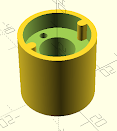
Here's the OpenSCAD design for the anti-backlash system.  two of the lead screw nuts were modified slightly to make this work:  two of their fixing holes were cut into slots so that they would engage the two lugs visible at the top of this part, preventing them from rotating with the lead screw whilst allowing the small vertical movement needed to allow the spring to push them against the thread.

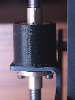
Here's the finished item in-situ.  Next time I might make it so you can see the spring inside.


Tuesday 23 June 2020

More 3d Printer Modifications

New controller for the Copymaster.


At the end of last year, the controller in my Copymaster 300 decided to kill itself by the classic method of having a dodgy ground connection, which then led to a ground loop in the USB link to the raspberry Pi which was controlling it via OctoPi.  This killed the USB-serial adapter on the board, and also the USB ports on the Pi.  The rest of the Pi still worked, including WiFi, and it's now relegated to controlling some LED pixels instead.  Don't need a USB port for that.  So a new controller board had to be found & installed.  After a bit of browsing the internet and watching YouTube videos (I recommend this Aussie chap who goes by the handle of  'teaching tech' for good instruction in all things 3D printing.

My research led me to conclude that there was really no point in trying to replace the board with another just like it or anything based on an 8-bit microcontroller when much more capable 32-bit controllers were readily available and not very expensive. Especially if you're willing to take a punt and order one direct from China via Aliexpress or Banggood or any of the other online outlets.  I chose the BigTreeTech SKR V1.3 controller and a set of TMC2208 stepper drivers plus a TFT24 display.  You can get these from via Aliexpress from BigTreeTech's 'store', which reduces the possibility of ending up with a fake. 

I won't go into detail about the process of setting the thing up and compiling the firmware (Marlin V2.something), as it's much better covered in Teaching Tech's own video on the subject.

I will mention that, perhaps obviously, neither the board itself nor the screen would fit neatly into the spaces of their predecessors, the mounting screw holes are in the wrong place.  I anticipated this, and but was confident that I could come up with something, made on my other 3d printer, that I could mount the new boards on and then mount that where the old ones were.  Turned out I was right.  I had to leave a USB cable plugged into the controller and dangle the other end outside, but I expected that too - not much chance of a completely different board having any of the connectors in the right place for the case panel cut-outs.

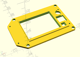
Here's the design for the controller board adapter.  The four larger diameter holes fit over the mounting pillars for the original board.  The one on the bottom right is taller because that also functions as a mouting pillar for the new board, along with the three smaller diameter pillars.


Here's the display board adapter.  The TFT24 is smaller than the original display, and both the screen and the encoder will fit inside the area of the original.  The part that stands proud of the main structure fits inside the panel cut-out for the old screen, with the new screen inside that.  The smaller square hole is for the reset switch, the larger one for the encoder body (the shaft just misses the edge of the raised area).  The circular hole is for the beeper.  Once again, the four large holes fit over the original mounts and the smaller ones are for the mounting screws for the new board.  The TFT 24 goes in there face up.

OctoPi

Still with the Raspberry Pi theme, for the last year or so I have been using Octopi to control both of my 3d printers.  Octopi is the Raspberry Pi version of Octoprint, which allows a host computer to send instructions to and receive telemetry from a 3d printer.  This is done through a web-based user interface, i.e. any device running a web browser on the same network as the printer can can simply navigate to 'http://<host name of computer running Octoprint>.local'  or 'http://<ip address of computer running Octoprint>' and see an interactive web page which will let them control the printer and monitor its progress.  If the Octoprint host has a webcam, that can be used to make time-lapse movies of the printing process.


For more details, see https://octoprint.org/

The two controlling my 3d printers connect to my wifi network, which works just fine whilst they're at home, if they were to be taken elsewhere then they'd need to be reconfigured to work on their own or on some other network.  Recently, I built a system for a friend which used the same trick as the mustard tin music players and the lightwand - provide an access point with DNS and DHCP servers so that a browser-equipped device can connect to it's little network and provide a user interface just about anywhere.

See https://thepi.io/how-to-use-your-raspberry-pi-as-a-wireless-access-point/  for a guide on how to set up an access point.

Shutting Down A Raspberry Pi

You can probably tell from the other posts in this blog that I'm a big fan of the Raspberry Pi microcomputer and have used it for several of my projects, usually without such niceties as a keyboard, mouse or monitor.  Using it in this way raises the issue of how to shut it down nicely so as not to avoid corrupting its boot disc (i.e. the SD card) by switching off the power suddenly.  My standard approach to this is to use a gpio pin to look for a signal to shut down the system.  I also find it useful, or at least comforting, to use another gpio pin to make an LED flash to indicate that the Pi is running and another one to light another LED to indicate that shutting-down is in progress.


When the Pi starts up, it runs a Python program called 'ShutdownCheck.py'.
ShutdownCheck.py assigns two gpio pins to be outputs, one for a red LED, one for a green LED, plus a 3rd gpio pin as an input.  The input pin is pulled high by the SoC's internal pull-up resistor, and can be pulled low by connecting it to ground through a simple momentary action switch, such as the type found in obsolete mice an on the front panels of outdated PCs that you found in a skip.  The LEDs' anodes are connected to output pins, their cathodes through a common resistor to ground  ShutdownCheck.py toggles the state of the output pin with the green LED and checks the input pin.  If the input pin is still high, it goes to sleep for a few seconds before looping back to toggle the green LED and check the input pin again.  If the input pin has gone low, i.e. the switch has been actuated, then the program sets the red LED's output pin high, sets the green LED's pin low and issues the command 'sudo shutdown -h now' - which will shut down the system.

A small variation on this, which I used recently because I had some 3-colour common-cathode LEDs, was to have the green & blue LEDs light up alternately until the shutdown request is received.  The python code for that version is shown below. 


# Python Script to check for shutdown request, alternate blue
# and green LEDs when running and light a red LED when shutting 
# down.  When red LED goes out again, Pi can be powered-off.
# Works well with a common-cathode RGB LRD.

import RPi.GPIO as GPIO
from os import system
from time import sleep

# set up GPIO pins to check for shutdown request
# and to light up LEDs.  Alternating Green/blue LEDs when active
# red LED during shutdown.  Note sdcheck is active
# low, i.e. grounded through switch to shut down.

sdcheck = 26
redled = 19
grnled = 13
bluled = 6

GPIO.setmode(GPIO.BCM)
GPIO.setup(redled,GPIO.OUT)
GPIO.setup(grnled,GPIO.OUT)
GPIO.setup(bluled,GPIO.OUT)
GPIO.setup(sdcheck,GPIO.IN, pull_up_down=GPIO.PUD_UP)

green_on = 1
blue_on = 0

while True:
green_on = (green_on+1) % 2
blue_on = (blue_on+1) % 2
GPIO.output (grnled,green_on)
GPIO.output (bluled,blue_on)
if not (GPIO.input(sdcheck)):
  print("Shutdown request received")
  GPIO.output(grnled,GPIO.LOW)
  GPIO.output(bluled,GPIO.LOW)
  GPIO.output(redled,GPIO.HIGH)
  system("sudo shutdown -h now")
  break
sleep(5)
I inverted the logic of the shutdown request (i.e. low input, not high, is interpreted as the command to shut down) as it does not need to use any of the powered pins that would be necessary for the 'normal' protocol, just the gpio pins and ground.

I've settled on using the four (or five for the r,g,b version) pins at the bottom left corner of the gpio header, as seen with the USB ports at the bottom and the gpio header on the right, as shown in the illustration right. Below is a photo of a switch plus red & green LEDs built onto a small header plug.