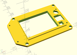
New controller for the Copymaster.
At the end of last year, the controller in my Copymaster 300 decided to kill itself by the classic method of having a dodgy ground connection, which then led to a ground loop in the USB link to the raspberry Pi which was controlling it via OctoPi. This killed the USB-serial adapter on the board, and also the USB ports on the Pi. The rest of the Pi still worked, including WiFi, and it's now relegated to controlling some LED pixels instead. Don't need a USB port for that. So a new controller board had to be found & installed. After a bit of browsing the internet and watching YouTube videos (I recommend this Aussie chap who goes by the handle of 'teaching tech' for good instruction in all things 3D printing.
My research led me to conclude that there was really no point in trying to replace the board with another just like it or anything based on an 8-bit microcontroller when much more capable 32-bit controllers were readily available and not very expensive. Especially if you're willing to take a punt and order one direct from China via Aliexpress or Banggood or any of the other online outlets. I chose the BigTreeTech SKR V1.3 controller and a set of TMC2208 stepper drivers plus a TFT24 display. You can get these from via Aliexpress from BigTreeTech's 'store', which reduces the possibility of ending up with a fake.
I won't go into detail about the process of setting the thing up and compiling the firmware (Marlin V2.something), as it's much better covered in Teaching Tech's own video on the subject.
I will mention that, perhaps obviously, neither the board itself nor the screen would fit neatly into the spaces of their predecessors, the mounting screw holes are in the wrong place. I anticipated this, and but was confident that I could come up with something, made on my other 3d printer, that I could mount the new boards on and then mount that where the old ones were. Turned out I was right. I had to leave a USB cable plugged into the controller and dangle the other end outside, but I expected that too - not much chance of a completely different board having any of the connectors in the right place for the case panel cut-outs.
Here's the design for the controller board adapter. The four larger diameter holes fit over the mounting pillars for the original board. The one on the bottom right is taller because that also functions as a mouting pillar for the new board, along with the three smaller diameter pillars.
 Here's the display board adapter. The TFT24 is smaller than the original display, and both the screen and the encoder will fit inside the area of the original. The part that stands proud of the main structure fits inside the panel cut-out for the old screen, with the new screen inside that. The smaller square hole is for the reset switch, the larger one for the encoder body (the shaft just misses the edge of the raised area). The circular hole is for the beeper. Once again, the four large holes fit over the original mounts and the smaller ones are for the mounting screws for the new board. The TFT 24 goes in there face up.
No comments:
Post a Comment